Duct fans: why they are needed, what they are, how to install. Exhaust fan - efficient and reliable
A duct fan is one of the most effective ways to improve air exchange in a room. This device serves as the main element of the ventilation system, is mounted in the ventilation duct and drives air flows through it.
Duct fan: what is it?
What is needed to ventilate the room? Based on the root of the word “to ventilate,” we can say that this is wind, that is, a flow of air. In the ventilation system, “wind” is artificially provided using a duct fan. The advantages of such a unit are as follows:
- installation versatility– a duct fan can be installed in any room: in residential buildings, industrial or public buildings. In addition, the device can be hidden behind a suspended ceiling, which makes the interior design more thoughtful;
- ease of installation– installation of the household version does not require the help of a specialist;
- quiet operation of the device– on average the noise level reaches 30–40 decibels;
- ease of maintenance– it is enough to clean the blades and body of the device from dust once every six months or a year;
- continuity of work- unlike less reliable ventilation methods - for example, the same ventilation - the fan can operate uninterruptedly in the selected mode and with a certain power;
- reliability– modern devices are equipped with a function to protect the motor from voltage surges, so the risk of breakdown is minimized.
No matter how good this device is, it still has one drawback: it is not designed for filtration. If the room needs not only fresh, but also clean air, you need to turn to other climate control equipment for help - for example.
The duct fan is controlled manually or automatically depending on the model. If you want to install a toilet, you can make it turn on with the light: to do this, you need to open one power wire and connect it to the light switch. Another option is to install a double switch, one key of which can be connected to the light, and the other to the unit itself.

Let's see what parts the device consists of:
- actually frame products. It is often made of galvanized steel: this way the body can withstand heavy loads and become resistant to corrosion. However, high-quality plastic is also suitable as a material for household needs. For the purpose of sound insulation, the walls of the housing are mainly made multilayer;
- Working wheel, which is responsible for the performance of the device;
- electric motor, with the help of which the wheel operates;
- blades, or paddles– during operation they rotate, collide with air and throw it in the desired direction;
- impeller– the rotating part of the device to which the blades are attached;
- decorative grilles, which are installed on wall surfaces and protect the air duct from debris;
- thermal protection, allowing the device to operate in conditions of temperature changes.
Some exhaust fans also have check valve, which prevents air from moving in the opposite direction, that is, from the street to the room. This happens if the device is turned off or broken and if the air temperature at home is lower than outside. Due to pressure differences, air moves from the street into the room. But the valve blocks the air flow and prevents it from getting inside.
The check valve comes in three varieties:
- passive– closes only under the influence of gravity. The efficiency of such a valve is quite low, and these days it is not in great demand;
- controlled– runs on electricity, opens and closes using a special sensor;
- self-closing– closes simultaneously with the cessation of air flow. It is often used for the toilet or kitchen.
The following can be distinguished stages of work devices:
- The impeller, rotating, creates an area of low pressure;
- Under pressure, air is sucked through the grille;
- The air flow hits the blades, where the pressure increases;
- Under pressure, air moves through a network of air ducts in the desired direction;
- To prevent the engine from overheating and the device from malfunctioning, thermal contacts open the electrical circuit at an excessively high temperature.
There are several criteria for classifying duct fans.
By purpose:
- Exhaust– with their help, exhaust air is removed.
- – they allow you to organize air flow.
- Reversible duct fan, changing the direction of movement of the rotor and impeller, is capable of simultaneously supplying “new” air and removing “old” air.
By form:

- Round– These are duct fans for round air ducts. They can be mounted in a flexible air duct, which expands the possibilities of designing a ventilation system.

- Rectangular– duct fans for rectangular air ducts.

- Square– such models are not very popular, as they take up more space and have greater resistance.
By design:

- Axial duct fan has a cylindrical body. In the housing, the blades are mounted on the axis of the electric motor, along which the air moves. As a rule, axial devices are the quietest. They have a small power, but it is enough to provide ventilation in small rooms; This type is also characterized by ease of installation. Therefore, these models are used for domestic needs. True, some of them have a high noise level, reaching up to 50 dB.

- Radial– unlike axial fans, in radial duct fans the air masses do not move along the axis of the electric motor. When the impeller rotates, the air entering the blades moves towards the periphery of the impeller in the radial direction and is thrown back under the influence of centrifugal force. The slope of the air flow depends on the location of the device blades. The blades can be directed forward or backward - in the second case, the operating power is reduced, but at the same time the noise level and energy consumption are reduced. Radial models are compact, so they can be installed in almost any air duct.

- Diagonal fans combine technologies of axial and radial models; in them, the air flow moves along the axis and then changes direction to radial. Thanks to the combination of directions, this type is extremely effective, while it is compact and almost silent. It is more often used in industry than in everyday life.

- In diametrical (tangential) duct fans air moves around the perimeter of the impeller. They are mainly used for highly specialized needs, for example, in air curtains, special technological equipment, air conditioners, etc.

- Duct centrifugal fans appeared on the market relatively recently. Due to the influence of centrifugal forces, they are distinguished by high power and relatively silent operation. They are also, as a rule, the most compact - so if you are faced with an urgent issue of saving space, centrifugal models are the best option.
By purpose:
- Household, as you might guess, are used in everyday life. Their power is only enough for small rooms.
- Industrial models have high power and often impressive sizes. During operation they can make a lot of noise.
According to operating conditions:
- Common use– this type includes models designed to work in natural conditions.
- Special purpose. Among them we note the following subspecies:
- Duct smoke exhaust fan designed to work in fire conditions. It is equipped with reliable protection against overheating; its body is made of materials that do not deform at temperatures above +600 degrees.
- Explosion-proof fan helps to organize the exhaust of air with explosive and flammable impurities. Such models are intended for enterprises where work with explosive substances is carried out.
- Heat-resistant duct fan used for removing steam from baths and saunas or air masses from rooms with fireplaces and stoves or from industrial enterprises.
- Dust fans used in rooms where the air contains a large amount of impurities and solid particles.
They are also popular silent duct fans. The device should “sound” no louder than 55 decibels - this is not harmful to hearing. Of course, it will be better if the device operates even quieter, so as not to distract your attention - within 30–40 dB.
Silent models still make noise, but no louder than 25 dB. Quiet operation of the fan is achieved in the following way: the manufacturer integrates gaskets and high-precision bearings into the design of the device, thanks to which the electric motor stops vibrating, and also selects the number of blades and calculates their angle of inclination to prevent vibration of the air flow.
To make the fan operation even quieter, you can line the ventilation shaft with sound-insulating materials and install a silencer behind the housing.
How to choose a duct fan
When choosing a duct fan, you should pay attention to the following technical characteristics:
- Variety. You should purchase a device depending on the purpose you need, shape, dimensions, etc.
- Performance, that is, the volume of air that passes through the device in a certain time. You can calculate the required performance using.
- Noise level. For an apartment, for example, silent fans are best suited, but for technical rooms where people rarely visit, the quiet operation of the device can be neglected. By the way, the degree of noise can be determined by the impeller blades: if they are bent back, the device will most likely make almost no sounds.
- Air flow speed. In everyday life, the optimal speed is 11–14 m/s. If this parameter is less than 11, then the efficiency of the device will be minimal, and if it is more than 14, then the noise level may become excessively high.
- Functionality. If the ability to set the operating time of the device, the presence of a check valve or other parameters is important to you, pay attention to this when purchasing.
- Safety, that is, protection from dust and moisture. A waterproof housing is especially important for the bathroom and kitchen: moisture getting inside the housing can cause a short circuit.
Evaporation and distillation processes are used in a variety of industrial applications. Whether in the chemical, food processing or water treatment industries, the most effective way to reduce energy costs is through the use of mechanical vapor recompression fans.
TLT-Turbo GmbH has developed a range of steam compressors that meet and exceed all modern standards, as do many of our products.
MVR Turbo Fan
We reduce operating costs.
A number of factors play a critical role in accounting for and amount of potential savings:
1. Best selection and design of the fan
The correct selection of a fan for specific requirements is guaranteed thanks to the wide range of TLT-Turbo sizes. This is important to achieve maximum efficiency.
2. Proper temperature rise
An increase in temperature up to 9°C is quite possible with TLT-Turbo steam compressors. Values higher are possible depending on the operating point. What is important is that steam compressors can be installed in cascade and the temperature increased even higher. It should be remembered that the higher the pressure and temperature, the more the efficiency of the steam compressor can drop, so it makes sense to install another steam compressor and thereby reduce energy consumption. This and other factors are subject to discussion on a case-by-case basis.
3. Use of energy-efficient motors and emergency situations
If there is such a requirement, we can offer our fans with optimally matched motors and variable speed drives from well-established manufacturers.
4. Long service life at low running costs
TLT-Turbo GmbH has something special in store for you in terms of service life and operating costs. All mechanical vapor recompression fans are equipped with modern maintenance-free hybrid ceramic bearings. These high-tech bearings, which until now have been mainly used in wind turbines and machine tools, have a lifetime lubricant supply and have a service life longer than standard bearings. Since no lubrication is required, regular oil changes are completely eliminated.
Made to order for your project, the way you want it
All fans are manufactured and equipped with different materials, such as duplex or super duplex stainless steel impellers, or even titanium - and this is a design created specifically for your application.
You can find a brief description of our mechanical vapor recompression fans - TLT-Turbo MVR fans (vapor compressors) - in our brochure, which is available for download at the top of the page. Or better yet: why not call or write to us right away? All contacts are below.
The special-purpose fan VO-60/250B is designed to create circulation of water vapor containing a small amount of impurities of phenol, hydrogen sulfide and alkalis in dephenolizing scrubbers. The VO-60/250B fan is equipped with technological lines of coke plants. The VO-60/250B steam fan is a special-purpose machine, and its use in other technological installations is not allowed.
The VO-60/250B fan can be used in temperate climates in rooms with natural ventilation without artificially controlled climatic conditions, where temperature fluctuations and exposure to sand and dust are significantly less than in the open air, or in tropical climates under a canopy or indoors, where fluctuations in temperature and air humidity do not differ significantly from fluctuations in the open air and there is relatively free access to outside air (climatic modification U and T, placement category 2, GOST 15150-69). The ambient temperature should not be lower than -30°C; the maximum permissible temperature of the moved air at the entrance to the VO-60/250B fan should not exceed + 105° C.
Taking into account the high aggressiveness of the transported medium, the impeller and volute of the VO-60/250B fan, which are in direct contact with this medium, are made of corrosion-resistant steel sheet grade 08X13 (GOST 5632-72). All other assembly units and parts are made of carbon steel (GOST 380-71) and cast iron (GOST 1412-79).
Technical characteristics of the fan VO-60/250B
| Specifications | VO-60/250B |
| Impeller diameter, mm | 920 |
| Moment of inertia of the rotor, kg∙m 2 | 34 |
| Rotation speed, rpm | 1500 |
| Aerodynamic parameters at a medium density at the fan inlet of 0.661 kg/m 3 | |
| Productivity thousand m 3 / h | 60 |
| Total pressure, yesPa | 305 |
| Shaft power, kW | 80 |
| Rated rotation speed, rpm | 1480 |
| Maximum efficiency % | 62 |
| Total sound power level, dB | |
| discharge noise | 125,5 |
| suction noise | 125,5 |
| noise from the case | 190 |
| Overall dimensions at ψ=90° (without electric motor), mm | |
| length | 2920 |
| width | 1800 |
| height | 1870 |
| Weight (without electric motor), t | 1,66 |
The fan for water vapor VO-60/250B is shown in Fig. 1.
Design of fan VO-60/250B
The fan design is:
- Working wheel,
- snail,
- suction pipe,
- foundation frame.
The VO-60/250B fan impeller is a riveted structure consisting of an impeller and a hub. The impeller has 32 forward-curved leaf blades located between the main and covering flat disks. The impeller blades are stamped and have a flange for fastening to the disks using rivets. The cast steel hub is attached to the main disc with rivets.
The impeller and hub assembly is mounted on the chassis shaft using a key, a protective washer, a lock washer and a special nut screwed onto the end of the shaft. A protective washer and a special nut, made in the form of a cup with an internal thread (“blind” nut), protect the end of the chassis shaft from direct exposure to the moving aggressive environment.
The Ukrventsistemy fan plant carries out static and dynamic balancing of fan impellers. The running gear of the VO-60/250B fan consists of a forged shaft, rolling bearings located in a common housing with a horizontal connector, and an elastic sleeve-pin coupling connecting the machine shaft directly to the electric motor shaft. The shaft neck, located directly behind the impeller and in contact with the moving aggressive medium, is closed with a sleeve. The VO-60/250B fan housing on the electric motor side contains a thrust bearing (double angular contact ball bearing). The support bearing can move in the housing, as a result of which temperature changes in the length of the chassis shaft are compensated. For ease of repair, it is possible to dismantle the bearings towards the coupling, i.e. without removing the impeller from the shaft. The common body, cast from cast iron, eliminates warping during operation and reduces vibration of the bearings.
Lubrication of the running gear bearings of the VO-60/250B fan - crankcase type - is carried out with oil located in the cavities of the VO-60/250B bearing fan housings (oil bath). The shaft seal of the running gear of the VO-60/250B fan is a combined centrifugal-gland seal, consisting of rubber cuffs and oil release rings that prevent oil leakage. The oil level in the oil bath is controlled by a level indicator. To cool the oil, a coil is mounted in the bearing housing, located in an oil bath. Cooling water circulates through the coil, entering from one side of the housing (see assembly in Fig. 1). The cooling water flow rate must be at least 0.5 m3/h per fan VO-60/250B: the water temperature at the inlet to the coil must not exceed +33° C for climatic version U and +40° C for climatic version T. When the ambient temperature drops below 0°C, the water cooling system is turned off and water is removed by blowing the coils with compressed air or steam.
The maximum permissible steady-state temperature of the VO-60/250B fan housing of the chassis bearings under operating conditions should not exceed +70° C. The temperature of the VO-60/250B fan housing of the bearings is controlled by two resistance thermal converters type TSP-085 with a length of immersed part of 60 mm, for installation of which sockets are provided in the chassis housing. The sockets for thermal converters allow the installation of bearing housings; a graphite seal is provided. The seal of the VO-60/250B fan is designed in the form of a floating oil seal, which makes it possible to compensate for the thermal expansion of the volute.
To ensure the necessary rigidity, gussets are welded between the inner surfaces of the support legs and brackets. The fan volute VO-60/250B is installed with support feet on the foundation frame and attached to it using bolted connections.
The VO-60/250B fan is manufactured in only one version - with a volute rotation angle of ψ=90°. The angle ψ is measured from the horizontal plane in the direction of rotation of the impeller. The suction pipe is a cylindrical shell, obtained by rolling, to which a flange is welded on the side of the suction opening for connecting the VO-60/250B fan to the duct. The suction pipe is inserted into the diaphragm hole concentrically with the axis of rotation, and is welded into the diaphragm to a depth that ensures the required axial clearance between the outlet section of the suction pipe and the inlet section of the impeller. The sealing unit is not provided in the VO-60/250B fan, since it does not have a significant effect on improving the aerodynamic properties of the VO-60/250B fan (with sheet impeller blades curved forward).
The VO-60/250B fan does not have special controls for regulating the performance and the developed total pressure. If necessary, the consumer is obliged to manufacture and install a gate device (damper) in the suction section of the duct.
The common foundation frame is a welded structure made of sheet and profile steel. Serves for installation on it in a single delivery unit of the electric motor, chassis bearing housing, clutch guard and fan volute VO-60/250B. The frame is attached to a common foundation with foundation bolts. For the layout of the foundation bolts, see Fig. 1 View B.
The performance, total pressure, shaft power and efficiency of the VO-60/250B fan are determined for various operating modes according to the aerodynamic characteristics (Fig. 2).

The total sound power levels of the VO-60/250B fan are determined by the noise (acoustic) characteristics (Fig. 3).
The VO-60/250B fan is driven by closed single-speed asynchronous electric motors of types 4A and AI (Table 2).
Evaporation of liquid in a closed circuit Process steam (evaporation) resulting from industrial processes is removed by means of a radial fan (steam compressor) to a higher temperature, and therefore energy level, and then returned to the circuit as fresh heating steam. The energy of the steam is not lost; it is only necessary to additionally supply the energy required to increase the temperature. Since energy costs have risen sharply in recent decades, everyone has been striving to reduce fossil fuel consumption and carbon dioxide emissions, as well as the still high steam consumption of these processes.
These goals can be achieved through mechanical vapor recompression, as recent developments in this process have made it an economical and reliable technology used in processes such as evaporation, distillation, crystallization and drying.
The closed process allows temperature-sensitive liquids, such as milk at approximately 60°C or even blood plasma at 35°C, to be evaporated under high vacuum. At the same time, valuable components of the final product (for example, milk powder) are preserved and the quality, and with it the cost of the product, increases.
Areas of use
At the beginning of its development, mechanical vapor compression was used mainly in the dairy industry. Subsequently, the process found wide application in other areas, for example in processing and/or production:

|
|


Areas of use
The Piller steam compressor is a high-tech equipment that is highly standardized. No other product from Piller Industrieventilatoren GmbH has so many design innovations. Thanks to standardization, the basis has been laid for cost-effective solutions that can be implemented very quickly.
Bearing assembly To ensure long-term reliability and reduce vibration to almost zero, Piller developed a one-of-a-kind Piller-Quetschöldämpfung bearing system, for which it subsequently filed a patent. This bearing assembly, which is used with both rolling and plain bearings, is designed to operate in supercritical conditions.
This means that the stiffness of the bearings is no longer a significant factor in the calculations, and therefore the unwanted and critical dependence of the rotor-wheel system on vibration that destroys the bearings can be significantly reduced. Since the stiffness of the bearings is now of secondary importance, the bearing assemblies are precisely sized for greater reliability in response to the loads encountered (load factors) and peripheral speeds.
Typically, a smaller bearing assembly with a higher permissible speed can be used in this way. For more information, see our brochure “Fans in the Critical Range”. Shaft seal Depending on the operating conditions, different shaft sealing principles are used.
In general, they differ in the following operating conditions:
- The process takes place in a high vacuum of 50 mbar< Pabs, < 200 мбар
- The process occurs at an excess pressure of 1 bar< Pabs
- The process takes place in high vacuum without a sealing medium
Control devices
The basic kit of the Piller steam compressor includes an electronic control device. Touch sensors are located in the main terminal box and record the following parameters
- Case temperature
- Bearing temperature
- Fan shaft vibration level
- Rotation frequency
- Oil temperature
- Oil level
- Oil volumetric flow
- Oil pressure
- Condensation level at the bottom of the case
|
|
|
|
|
|


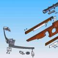 DIY long-range crossbow (102 photos)
 PVC profiles for window and door blocks technical specifications
 Peyote where. Peyote cactus. The most exotic plant. Peyote cactus propagation