LED chandelier controller repair. How an LED chandelier with a remote control works and works: do-it-yourself repair experience. Benefits of remote control

Here I will talk about the design and malfunctions of radio-controlled chandeliers with halogen and LED light sources.
Despite all their diversity, almost all chandeliers with a control panel have a modular design and are assembled from the same type of electronic components.
Here are the main ones:
Radio-controlled relay and control panel;
LED lamp;
Lamp with halogen lamps.
Depending on the design, chandeliers can be either pure LED or combined with halogen lamps. Thanks to the radio-controlled relay, you can turn on either all the lamps, or only the LED or halogen part.
Where to buy parts and ready-made blocks for repairing a chandelier with a remote control?
Hereinafter I will refer to the well-known online store AliExpress. It is there that you can find all the necessary spare parts and units, which will be discussed further. My choice is due to the fact that there is a large selection and low prices.
In radio markets, as well as in electrical goods stores, similar products are more expensive - their prices are simply “inflated,” although the quality is the same. Therefore, for those who know how to buy on the Internet, I advise you to pay attention to this. The only disadvantage of such purchases is the rather long delivery (1-2 months), although this largely depends on the seller. I have already talked about how to search and order goods on Aliexpress.
Radio controlled relay.
The radio control of the chandelier is organized using a radio relay, which is designed to be powered from a 220V power supply. Depending on the “steepness” of this block, it may contain from 2 or more electromagnetic relays, which are designed to switch a load with a power somewhere up to 1 kW.
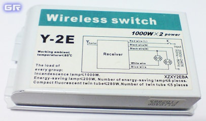
This is what this block looks like. It is he who receives commands from the wireless remote control and turns on a certain section of the chandelier (halogen or LED lamp, or both). Pay attention to the inscriptions and typical connection diagram, which is shown on the unit body.
Here's what's inside this box.

A decoder chip is hidden under the green YDK-30 RF module HS153SP-J. The two black things that take up a third of the circuit board are electromagnetic relays.

The RF module itself.

Here is a schematic diagram of a radio relay for 2 control channels, model Y-2E.

The diagram is drawn by hand, so there may be errors. Similar radio-controlled relays powered by a 220-volt power supply also have the same circuitry.
A radio module is installed on the printed circuit board (marked YDK-30). It is made on SMD elements and, apparently, has a fairly simple circuit design.
The radio receiver circuit is powered using a “quenching” capacitor circuit. Excess mains voltage is suppressed by ballast capacitor C2. This implementation of the circuit is simple, but very dangerous, since there is no galvanic isolation from the power supply. Voltage stabilization is implemented using zener diodes VD5, VD6 ( 1N4741A) at 11 volts.
In addition, over time, many encounter incorrect operation of the radio relay. And it is connected precisely to the ballast capacitor C2.
Here is a message from one of the site visitors who encountered this problem and discovered its cause:
"These radio modules have a typical breakdown - after some time of operation (2-3 years), only 1 channel works normally; when you turn on the 2nd or 3rd remote control, it stops responding to button presses, that is, you can turn on all channels, but after that it cannot be controlled only with a switch on the wall or by bringing the remote control closer than 0.5 meters to the chandelier.
This is due to the degradation of the film capacitor in the radio relay power supply. In the photo it is indicated by a red arrow.

The capacity of this capacitor is usually 1-1.5 µF, the operating voltage is not lower than 250 volts (marking: 105j250v, which means 10*10 5 picofarads or 1 µF). Replace with similar ones of domestic or imported production with a capacity NOT greater than that of the one you have installed (more is possible, but there is a high probability that the zener diode will either heat up wildly or burn out immediately."
Despite the good appearance of the radio relay, it sometimes causes the halogen part of the lamp to not work. The fact is that the place where the electromagnetic relay is soldered onto the printed circuit board degrades over time. Either because of poor soldering, or because of the high inrush current that is generated when the halogen lamp is turned on.
Wireless chandelier control panel.

The RF control panel is also quite simple. There are 2 transistors on the printed circuit board ( S8550 And S9018) and encoder chip CS5211AGP. It encodes commands and transmits them to the sending node.

The buttons are designed in the same way as standard remote controls - there are no mechanical buttons, like tactile buttons.

Since the chandelier is assembled from blocks, the radio-controlled relay can be easily replaced. You can look for a new unit at an electrical goods store or order it online. Here is the link .
The relay block can have several control channels. For example, one includes the halogen part of the chandelier, the other includes an LED lamp. In this case, the radio-controlled relay has 2 control channels (2 way). If you need a relay with a large number of control channels, then take the one that is required. Here you can choose a module for 1, 2, 3 or 4 control channels.
In some cases, the radio-controlled relay unit can be completely disabled. This may be necessary when the unit itself is faulty and a suitable one is not available.
In this case, you can completely “throw out” the unit and turn on the chandelier using a regular power switch.
If you wish, you can assemble a chandelier with a control panel from an ordinary one. Or make the background lighting of the room, the main room and, for example, a street spotlight controllable from the remote control. To do this, you will need the same radio-controlled relay unit or, in other words, a controller with a remote control. At one time, at a wholesale base, I bought this ELEKTROSTANDARD unit for 3 channels (3 way).
This is the same set of wireless relays with a remote control only in blister packaging.

The set includes a remote control with a holder, a 12V battery for the remote control, and the unit itself has 3 channels. It is written that the remote control range is 8 meters. Each control channel is designed to connect a load with a power of up to 1 kW. For all channels in total - 3 kW.

The hardware itself was allegedly developed in Germany and assembled in China. In fact, its electronic filling is no different from the filling of those blocks that are widely used in Chinese chandeliers with a remote control. Only detailed inscriptions are in Russian, but everything is the same.

Halogen lamp.
To power halogen lamps (usually type G4), which are designed for a voltage of 12V and a power of 20W (watt) each, step-down pulse converters are used, which are called electronic transformer. This is what he looks like.

The insides of an electronic transformer.
![]()
Halogen light bulbs can be easily checked with a multimeter by measuring the resistance of the filament. Attention! Halogen bulbs should not be touched with your fingers! Only through a napkin or rag material.

In the particular chandelier that fell into my hands, for each electronic transformer there were 5 halogen lamps, each with a power of 20W. Halogen lamps connected in parallel. In total, one electronic transformer supplies 100 watts of power to the lamps.
Sometimes the electronic transformer in the chandelier fails. In this case, the part of the chandelier where the halogen bulbs are installed will not shine when turned on. In this case, you can replace the faulty electronic transformer. At the same time, it is worth first checking the serviceability of the radio relay itself, since it is through it that the mains voltage (220V) is supplied to the input of the electronic transformer.
An electronic transformer of suitable power can be purchased. We select a model for the required power.
Cheap halogen lamps can be selected from this link. We pay attention to the form factor of the lamps that are installed in your chandelier. Typically these are G4 halogen lamps with a power of 20-35 W.
LED lamp.
Implemented according to the simplest scheme. Here is his diagram, which was compiled by hand.

The circuit consists of so-called LEDs connected in series. In the chandelier I was considering, I counted 56 pieces. Depending on the design of the chandelier, there can, of course, be either more or less.
All this goodness, with the exception of the LEDs, is hidden in such a small box called “LED Transformer”, although the word transformer not appropriate here.
![]()
Printed circuit board "LED Transformer" - power supply with a quenching capacitor.

The LED Transformer is based on a power source based on a ballast (“quenching”) capacitor, and the LEDs powered by it connected in series(that is, one after another). Thanks to the circuit with a quenching capacitor, it was possible to get rid of the power transformer or switching power supply. Unfortunately, this simplification played a cruel joke. The reliability of such “transformers” leaves much to be desired.
It is not uncommon for this LED Transformer to fail. At the same time, many are faced with the problem of purchasing and replacing it. First, I’ll tell you how to choose a replacement, and then where you can buy them.
The first thing you need to determine when replacing a faulty LED Transformer is to find out how many LEDs it is designed for. A chandelier lamp, as a rule, consists of several dozen LEDs (white or blue). They can simply be counted.
You can also look at the block itself. On its body it is indicated for how many LEDs it is designed for. Usually this is an imprecise figure, for example, 66 - 80 pieces ( PCS). Sometimes this inscription is not indicated in any way, but is simply included in the marking of the block model. For example, like here.
![]()
Sometimes the number of LEDs is indicated on a sticker in a kind of table. Take a look.
![]()
I think it’s clear that you need to select a replacement “transformer” based on the number of LEDs in your lamp. You can select a suitable block or.
If the lamp in the chandelier is multicolored, that is, the color of the glow changes, for example, from red to blue, then in such a chandelier the LED Transformer is supplemented with a controller of two-color LEDs.
In addition to the power supply itself on the ballast capacitor (LED Transformer), it contains a microcontroller and control keys. The presence of such a controller allows you to control the color of the glow. On the body of such units, as a rule, something like this inscription is indicated: " RB Synchronous double controller", which loosely translated means: synchronous dual controller.
Reduction R.B. indicates the color of the LEDs. In this case Red- red and Blue- blue. It is worth noting that the LEDs for such controllers are not ordinary, but two-color. Their power supply may differ from the standard 3 volts and be around 5. Therefore, when replacing the LED Transformer, pay attention to the inscriptions. Perhaps in your case the block is not simple, but with a controller.
Since the standard LED Transformer is designed to operate from a 220V network, the input voltage is indicated on it (write AC220V, AC110/220V and similar combinations, where A.C. symbolizes "alternating current")
The output from which the LED circuit is powered is marked as OUTPUT DC3V LED. This abbreviation translates to "DC Output ( DC), voltage 3 volts". But, there is a catch.
The fact is that in electronics the standard supply voltage for one LED is taken to be 3 volts. For LEDs of different glow colors it is slightly different, but that is not the point.
The output of the LED Transformer will actually be much more voltage, since the LEDs in the lamp circuit are connected one after another (in series) and as a result, each of the LEDs will have about 3 volts, and for all of them in total - several tens of volts! That is why on the sales pages of the same AliExpress sellers indicate 3V*N in the description (where 3V is the average voltage on one LED, and N is their number in the circuit (lamp)).
Therefore, if you have 56 of them, then the voltage at the output of the LED Transformer will actually be about 3 * 56 = 168V! But, in order not to fool our heads, we decided to simply indicate how many LEDs a particular LED Transformer is designed for.
As already mentioned, the circuit design of the LED Transformer is very simple. The current at the output of such a block is unstabilized. Due to the fact that the voltage in the 220V household electrical network changes, it also changes at the output of the LED Transformer. As a result, excessive current may flow through the LEDs. It is well known that LEDs are very sensitive to current fluctuations.
This state of affairs leads to the fact that after a short time, they simply begin to burn out. Because of this, the entire circuit stops working, since they are all connected in series. Failure of even one of them leads to inoperability of all LEDs. They either blink all together, or turn on/off chaotically and unpredictably.
LEDs die very interestingly, as if not for good. They can shine more dimly, light up and go out unpredictably. This is like a reversible breakdown mode. Those familiar with electronics know that semiconductor diodes have this property.
It is worth noting that, as a rule, not just one LED becomes unusable, but 5 - 10 at once. Some continue to work, but with low light output. Therefore, it makes sense to replace them all during repairs.
Where can I get cheap LEDs? The cheapest ones are sold in China. In the AliExpress online store, I was able to find offers for 69 kopecks per piece (lot of 1000 pieces). There are also offers for 1 ruble/piece if you buy a batch of 100 pieces. Here is the link, choose. Just enough to repair the chandelier, and there will still be some left over.
The LEDs are easy to change; they are simply inserted with their leads into the connector. The only thing worth considering is the polarity. If you reverse the polarity of at least 1 LED, the entire circuit will not work.

To replace, you need to choose LEDs with a wide beam angle - they have a transparent body and a flattened lens. Like these ones.

Although these are also suitable, their glow is more pinpointed.

If you wish and have very modest skills in electronics, you can make almost any chandelier, purchased at the nearest electrical goods store, radio-controlled. To do this, you just need a radio-controlled relay powered by 220V.
Lighting is one of the main systems in the house, because it not only decorates the rooms, but also ensures comfortable work at any time. Among the wide range of lamps, special attention should be paid to the chandeliers on the control panel. This is a technically challenging device, but don’t be afraid to buy it. Anyone who reads this article will be able to install a lamp in their apartment and make minor repairs. Let's look at connecting a chandelier with a remote control and what it consists of.
Device
Any lighting device consists of three parts:
- frame;
- cartridge (1 or more);
- lampshade (1 or more).
The electrical part of most conventional lamps consists of power wires connected to the socket in which the light bulb is installed. This is the basis that remains unchanged. In this case, the supply voltage and type of current may differ depending on the type of lamps installed.
Smart chandeliers and chandeliers with remote control are distinguished by the fact that a signal receiver from the remote control and a lamp switching device are added to their circuit. Depending on the complexity of the lamp, they may not just turn on and off, but also, for example, have the ability to continuously adjust the brightness.
The chandelier can be installed:
- halogen lamps with a supply voltage of 12 V;
- 220 V lamps of any type (if there are no specific recommendations in the instructions);
- DC LED bulbs, or individual LEDs or assemblies;
- It is possible to use RGB chips to create decorative lighting or light music.
If the lamp simply turns the light on and off, then a radio-controlled relay box is used. If smooth regulation is provided, then for this purpose AC voltage regulators or PWM controllers are provided to regulate the DC voltage.
So, most often the electrical part of the chandelier on the control panel consists of:
- Receiver of control signals. Depending on the model, it can work in the IR range, at radio frequencies, for example, 433 MHz, via Wi-Fi or Bluetooth, in which case it can be controlled from a smartphone.
- Switching device. This is a device to which commands are sent from the transmitter; it includes a lamp or group of lamps. Usually this node is structurally combined with the receiver.
- Groups of light sources.
- If low-voltage halogen lamps, LED lamps or LED assemblies are used, then electronic transformers and 12 V power supplies are installed, respectively.
Radio relays in English are called Wireless Switch. To find this part in the chandelier body, look for a similar inscription on the body of the blocks.
Scheme
Let's look at a typical chandelier circuit with wireless control.
The illustration shows a diagram of a 220 V chandelier with lamps - this is the simplest option. There are no step-down power supplies or converters here.
This diagram more clearly shows the connection of the remote module to 4 groups of lamps.

Please note that it comes out:
- 2 wires for connecting to the network;
- 5 wires for connecting to the load (depending on the number of groups, the number of wires is 1 more than the number of groups - this is a common zero);
- 1 wire that is not connected to anything is the antenna, usually white, but may vary.
The neutral wire is common. There are two of them, one for connecting to the network, the other for connecting to the load, they can be swapped, they are soldered to one point on the board.
Appearance, the connection diagram is indicated on the case:
Inside such a module there is a board:

The blue elements are relays. These are switching elements; they supply voltage to the load. They have 12 V coils; to power them, a transformerless circuit with a quenching capacitor is implemented.
Here is the second diagram:

This is a chandelier with halogen low-voltage lamps and LED lighting. One of the most common options. In the middle part of the circuit for power supply are installed (from top to bottom):
- Power supply for LEDs (Led transformer), but judging by the diagram, this is a driver, 45 3 V LEDs are connected to it sequentially.
- 2 12 V electronic transformers for halogen lamps (Electronic converter), 5 12 V lamps are connected to the first, and 4 to the second. These lamps are connected in groups parallel.

Expert opinion
Alexey Bartosh
Ask a question to an expertIt is not possible to connect 12 V LED bulbs to electronic transformers, for several reasons. Firstly, the output of the electronic transformer is a high-frequency alternating current (LEDs operate at constant), and, secondly, these transformers usually have a current feedback circuit, which means that in order to start it, the load must consume some minimum current . Look closely at the diagram, there are 5 20W bulbs connected to the transformer, and low voltage LED bulbs are typically rated at 1-7W, most often in the first half of that range. Therefore, to convert a chandelier to 12 V LED lamps, you need to use 12 V power supplies; those used to power LED strips, as in the photo below, are also suitable.
 Power supply for LED strips
 Network connection
After purchasing a new chandelier with a control panel, its internal circuit is already assembled. You can check the correct connections of the circuit and make sure that it was assembled conscientiously by comrades from China, according to the information described above. If there are terminal blocks, be sure to check that all screws are tight. Inside you will see this picture
If everything is in order and connected well, then you only have to connect the power wires (phase and neutral):
- Remove the old chandelier.
- Prepare the wires for installation and strip them.
- Connect the wires from the new chandelier; for this it is convenient to use Vago terminal blocks or NShVI lugs, but do not forget to insulate them.
Expert opinion
Alexey Bartosh
Specialist in repair and maintenance of electrical equipment and industrial electronics.
Ask a question to an expertDon’t forget to turn off the voltage at the input circuit breaker into the apartment or unscrew both plugs if you have old wiring and a meter. In general, the switch should break the phase wire - this means that there should be no voltage on the wires, but it is better to turn off the circuit breaker in case the switch is placed in the zero break. And there is less chance that someone will accidentally turn on the chandelier switch. After disconnecting, be sure to check that there is no voltage.
Typical faults and their elimination
If the lamp does not respond at all, then the first thing to check is whether the batteries in the remote control are dead. If everything is in order, you need to remove the lamp. Next check the radio relay.
The radio relay has 2 power wires - phase and neutral and several output wires, their number depends on the number of switched groups. If the chandelier has three groups of lamps plus LED backlighting, then the radio relay will have 4 output phase wires and a common zero. Accordingly, each chandelier will have a relay for the required number of groups.
If you are not very versed in electronics, the most you can do is check the voltage at the input of the unit. If there is voltage at the input, check whether voltage appears at the output terminals of the controlled groups after pressing the keys on the control panel. This can be done with a multimeter or a simple indicator screwdriver.
If the unit responds to signals from the control panel and voltage appears on the output wires of the relay, then the problem is in the light bulbs or their power supplies.
Please note that the relay block is supplied with a voltage of 220 V, such voltage also appears on the output wires, be careful.
All power supplies rarely fail at the same time; usually there is a lack of response from one of the groups of lamps. Then you need to figure out what type of lamps are used, find their power supply and replace it. If you are good with electronics, you can try to repair it. The simplest thing you can do is check the health of the fuse on the power supply board.
Be careful when purchasing replacement power supplies; if halogen lamps are installed, then when purchasing a transformer you need to determine the output characteristics. Usually they are indicated on the body, if there is no mark, look at what voltage the light bulbs are set to, what power and how many pieces in the group, usually there are electronic transformers with the characteristics:
- Input voltage – 220 V.
- Output voltage – 12 V.
- Power 100–200 W.
The same applies to power supplies for LEDs - replacements are selected that are similar to those previously installed.
Conclusion
The remote control chandelier is easy to use, and the block internal circuit makes it easy to repair. Usually their design is standard - several groups of lamps for lighting and decorative lighting with LEDs. Installing a chandelier in most cases is no different from ordinary lamps.
More and more LED technology is entering the home. It brought unlimited possibilities in the design and lighting of living spaces. The manufacturing company Garlen gained great popularity by creating chandeliers with a remote control. Garlen quickly became one of the leading Chinese lighting companies and remains so today.
Design and principle of operation
Before you begin repairing a chandelier, you should definitely familiarize yourself with the design of the lamp. Currently, several variants are usually produced:
- Lamp with incandescent lamps;
- Lamp with halogen lamps;
- Lamp with LEDs and LED backlight;
- Lamp with incandescent lamps and LED backlight;
- Lamp with halogen lamps and LED backlight.
Chandeliers with incandescent lamps are rare. There are a wide range of LED lamps with LED backlighting and chandeliers with halogen lamps and LED backlighting.
 Many manufacturers produce chandeliers with a control panel, but, as a rule, they consist of the same blocks: a radio signal receiving unit and LED control unit (control controller), an electronic transformer for powering LEDs (Led Transformer) or a similar one for powering halogen lamps.
Manufacturers install LEDs for chandeliers with a remote control for increased reliability, but they still fail. In order not to buy new lamps for your home, it is much cheaper to carry out the repairs yourself.
Controller
The controller is a chandelier control unit. The unit contains a radio module that receives commands from the remote control. Depending on the model, the block contains from two to seven electromagnetic relays, which supply power to the necessary electronic transformers, and thereby turn on various lines of LEDs or lamps.
Electronic transformer
 It is designed to power lamps or LEDs. The transformer blocks are similar in appearance to each other, but differ in markings. On the transformer for halogen lamps, usually designed for a voltage of 12V (volts) and a power of 20W (watts), there is an inscription on the sticker: input AC 220−240V, output AC 12V 120W. This means that five light bulbs can be connected in parallel to the block.
On Led Transforme for LEDs it is written: model lfr807 (66−80), input AC 220−240V, output DC 5V LED (LED supply voltage - 5 volts). The numbers 66−80 indicate the number of LEDs for which this Led Transforme is designed.
Typical malfunctions of the chandelier
Malfunctions associated with chandeliers equipped with remote control have characteristic features. The main breakdowns that often occur:
- Does not respond to the remote control;
- Does not respond to a stationary switch;
- A certain number of LEDs or halogen lamps do not light up;
- Several commands are executed from the remote control and stops responding to commands;
- Does not respond to either the remote control or the stationary switch.
No remote response
There may be several reasons. Take your smartphone, turn on camera mode, point the remote control at the camera and press the buttons. If it works, you will see a bright white blink on the screen. If not, then it needs to be repaired.
You can determine the cause of the problem by following these steps::
- Checking batteries;
- Checking the tracks of the remote control board;
- Checking and cleaning the board contact pads.
 You need to open the compartment where the batteries are installed and take them out. Check the battery voltage with a multimeter; if it is below normal, replace the batteries.
If the light device no longer responds to the remote control, take it and disassemble it, carefully look at the traces of the printed circuit board, solder joints - there may be ring cracks around them, if there are any, solder them. Clean the contact pads.
If the remote control works, then the reason is in the chandelier control controller. Remove the chandelier, take out the controller unit, disassemble it and you will see the RF receiver board. Check all capacitors on the board and solder contacts; it is advisable to replace all capacitors, since over time their capacity decreases and they leak. Check the contacts near the photocell, they are often lost; if necessary, solder them. Check the Chinese photocell for cracks.
If all detected problems are corrected, but the RF receiver does not work, it means that the RF receiver chip has failed. Replace the chip or buy a new RF receiver.
Incorrect operation from the remote control
If all modes work from a stationary switch, and from a distance the selected modes work first, and then the light element stops responding to commands, then the problem is in the control controller board. There are metal-ceramic capacitors on it that resemble thick pads - they are the ones that need to be replaced.
Problems with the fixed switch
If the chandelier turns on from the remote control and does not respond to the stationary switch, this means that the control controller is working properly and so are the electronic transformers. Otherwise, it would not work from the remote control, provided that the remote control and control controller unit are in good working order. You need to take a multimeter and ring all the connections of the switch to the controller unit, having first de-energized everything. Find the break and fix it.
LEDs and lamps do not light up
 If all the LEDs are not lit, it means the control controller is not working.. If a certain number does not light up, it means that one or more LEDs, or one of the two electronic transformers that powers its line of LEDs, has failed. The LEDs are connected in series, and if one burns out, the circuit breaks and the others do not light up either. Check the LEDs. Find the burnt one and replace it.
If halogen lamps are used, the electronic transformers to which they are connected must be checked. Then check the lamps themselves: they are usually connected in parallel and can be easily checked with a multimeter. Find the faulty one and replace it.
The lamp does not turn on
If the chandelier does not operate either from the control panel or from the stationary switch, most likely the chandelier control unit has failed. Usually, the chandelier control unit fulfills its purpose very reliably, but due to voltage drops, the microcircuit of the control unit fails, and the conductive paths on the board burn out. Open the unit while holding the board with one hand. In your other hand, take a magnifying glass, with which you carefully examine the metallized tracks for damage and microcracks. Damaged items can be restored.
Diagnostics and repair of LED chandeliers with a control panel does not cause any particular difficulties. You can save a significant amount of money by repairing the chandelier yourself and without the help of a specialist.
Modern technologies are constantly developing and improving. Ceiling chandeliers were no exception. Now you can control the lighting fixture remotely without going to the switch. Some remote control designs are available not only as push-button ones. With their help, you can give voice commands, which the lighting system carries out quite accurately. Thus, the design of a chandelier with a remote control has become a reality, and the options are especially popular.
Benefits of remote control
The main advantage of chandeliers with remote control is the ability to turn them on and off from a distance, without leaving your place. This is especially true for large apartments equipped with several lamps at once. Chandeliers can be controlled at distances of 30-100 meters, the signal can easily pass through walls, making it possible to turn off the lights in another room.
The appearance of these lighting devices does not differ at all from similar standard devices. Elements receiving the signal are completely invisible. The operating modes of each type of chandelier depend on factors such as the type and number of lamps, the presence of lighting with several primary colors. Therefore, the remote control has the ability not only to set the color, but also to smoothly change it.

The main lighting is also easily adjustable by turning off a few selected lamps or by dimming them. The control panel itself is the main element in the system, since without it control as such is impossible. However, if it fails, it can be turned on using a regular switch. The remote control has buttons that provide access to any of the lamp operation modes.

The remote control system can be purchased separately and integrated into almost any type of luminaire.
Selecting chandeliers with remote control
First of all, the choice is made according to the type of light source. The cheapest option is considered to be chandeliers with conventional incandescent lamps. Chandeliers designed for energy-saving, halogen and LED lamps are much more expensive. However, they have much higher efficiency and a longer service life. And their appearance is more sophisticated compared to conventional lamps.
Much depends on the power of the chandelier and the level of lighting. Depending on the room in which one or another lamp will be installed. A significant role is played by the range of the remote control, as well as the design and overall dimensions of the chandelier itself.
Methods of controlling lamps without the use of stationary switches are increasingly gaining popularity among the population. This is explained by the ease of use and the wide availability of kits that make it quite easy to switch already working chandeliers to remote switching off or on.
Manufacturers have now massively mastered the production of original lamps with LED lamps and garlands, which create beautiful lighting effects while saving energy.
You can use them without getting up from your chair or sofa using a small remote control.
The principle of remote control of lamps
The basis for remote control is the transition from those located on the walls of rooms and connected by wires to the chandelier and the apartment panel, to the use of radio control channels. For this purpose:
radio transmitter built into a small-sized and convenient remote control;
a radio receiver that receives commands from the user and transmits them to the executive unit;
electrical power systems for the remote control and receiver.
Structurally, the radio receiver is placed on the same electronic board with power supplies, logic and actuators on relay switches and is called in one word - “controller”. It is powered from the apartment electrical wiring, placed near the chandelier and connected to it with connecting wires.
The radio signal from the remote control, received by the antenna and amplified by the radio receiver, is processed by logic and sent to a switching unit that connects certain lamps.

Technical capabilities of remote control
All of the above elements may have a different set of functions and, accordingly, differ in design complexity and cost. Let's look at their characteristics using the example of a common budget version of the kit shown in the photo.

The remote and controller are designed to work together. They are tuned to one common frequency and, in addition, use a radio signal encryption algorithm specially created for them. This is done in order to exclude the control of the chandelier from the owners of other apartments using similar equipment.
But, you should understand that if one of these elements breaks down and needs to be replaced with another, you will have to buy a new remote control together with the controller.
The kit in question works with three autonomous lighting channels, each of which can have a load of up to 1 kilowatt, which is more than enough for home use even when using powerful incandescent lamps. However, when operating fluorescent or energy-saving lamps, it should be taken into account that their inrush currents are up to four times higher than the rated values.
To control the lighting channels, there are 3 buttons on the remote control: A, B, C, and the fourth D is designed to turn on the lamps or completely remove the voltage from them.
Removing this remote control from the controller at a distance of eight meters is quite enough for our apartments, although there are models of radio transmitters on sale that can control at distances of a hundred meters.
The remote control is electrically powered from a galvanic battery, which is included in the kit, and the controller is powered from the network via a unit built into the board.
The kit in question has one feature: the voltage of the phase and working zero of the apartment wiring must be connected to the controller input. If you turn it off and then turn it on from the switch with the remote control de-energized, the chandelier begins to glow, bypassing the radio channel.
This allows you to control the light of the chandelier without remote control of conventional wall switches, but at the same time creates inconvenience associated with possible unauthorized lighting at night or during the day.
A similar case can occur when the lamps are turned off by the radio remote control, and due to the occurrence of even short-term malfunctions in the power supply organization, consumers are disconnected and then turned on. The controller perceives the supply of such voltage as a command to start the lighting.
Designs of lighting installations for remote control
Control kits with remote control allow you to control the operation of any lighting fixtures. To do this, it is enough to select them in accordance with the technical characteristics:
operating and starting current;
mains voltage;
You can equip any old chandelier with incandescent lamps with a remote control: just install the controller into the electrical circuit and use the remote control.
Usually for this purpose they try to build in a controller board:
inside the protective steel cover of the chandelier, covering the wires of the lamp;
into the ceiling hole near the mounting hook;
in place of the switch.
The latter case is rarely used: it requires laying additional wires from the switch location to the illuminators.
Modern LED chandeliers can use combinations of different light sources:
additional illuminators that create special effects.

However, some sources may require their own power and control circuits. An example is that, when turned on, they begin to work according to pre-prepared algorithms.
Design of LED chandelier with remote control
Let's look at this question using the example of the model shown in the above photograph. It is available with a controller and remote control, allowing you to use the same four modes: A, B, C, D.

Thanks to its design, the chandelier allows you to create various light compositions. This is what one of them looks like.

For mounting on the ceiling, a standard fastening strip is used, which is attached to the load-bearing concrete slab using dowels and self-tapping screws. There are two holes made at the base of the chandelier through which the strip pins are threaded. Decorative nuts are screwed onto their threads, holding the weight of the structure through washers.
The base of a removed chandelier is usually made hollow to accommodate all electrical parts in its space and ensure their installation.

Highlighted in the photo:
power wires and protective PE conductor;
controller with antenna;
LED lamps and garlands;
scheme for creating special effects for additional lamps.
The controller mount is shown in more detail in the next photo. For clarity, the cover has been removed.

The lower box of the controller housing of this chandelier is firmly glued to its base. However, the board itself is not difficult to remove from there.

The following are clearly visible on the board:
three switching channels of channels A, B, C, which have outputs marked with blue, yellow and white wires;
channel for turning on and off the device;
radio receiver chip with antenna wire.
These same elements can be viewed from the back of the board.

Switching channels allow you to use all lamps simultaneously to create maximum illumination or set half the mode of their use along the internal or external circuit.
At the top of the photo you can clearly see that the red wire of the network phase is soldered to the contact of the track and routed along it according to the controller circuit. The working zero is specially made with two wires for a separate one:
use in a controller circuit;
power supply of lamps, garlands of lamps.
Hidden remote control features
Even a simplified version of the considered chandelier allows you to additionally use certain functions of the devices. You can free up at least one lighting channel and use it for other purposes, for example:
manipulate a separate group of spotlights;
open or close window curtains using an electric drive;
control the operation of the projector or other electrical devices.
More complex models of controllers and consoles can significantly expand the list of operations performed, carrying them out according to certain algorithms, carrying out:
color selection;
turning on certain groups of lamps;
brightness adjustment;
using a timer to control lighting on a schedule.
The remote control buttons discussed in the article are currently undergoing changes. They are beginning to introduce more advanced models with voice control.
Disadvantages of remote controlled chandeliers
Manufacturers of remote controls and controllers indicate the maximum operating temperature in the technical specifications for their products. For the devices shown in the photographs, it is 85 degrees. This is a very important characteristic that many owners simply do not pay attention to.
Any electrical components work well when the appropriate conditions are created for them. Microcircuits and semiconductor elements do not tolerate overheating and burn out. Many types of low-melting solders flow under increased heat.
Where is the controller located? The answer is simple: at the highest point of the ceiling, which is always the hottest. In addition, the board is placed in an unventilated metal box hidden in the chandelier body. Next, it remains to compare the load power of the lamps, especially with incandescent or halogen lamps, the heat they release, which is spent on heating the overall structure, and draw a conclusion about a possible reduction in the service life declared by the manufacturer.
For this reason, you should always evaluate the possibility of removing heat from the electronic components of the controller, or at least ways to control its temperature, which many owners do not do at all. In this situation, placing the electronics next to the chandelier, but excluding the thermal transfer of energy from the lamps to it, will be the most acceptable solution.
 How to quickly get rid of weeds in the garden and destroy the grass Using weeds in everyday life
 Types and principle of measurements
 Copper resistivity Units of electrical conductivity